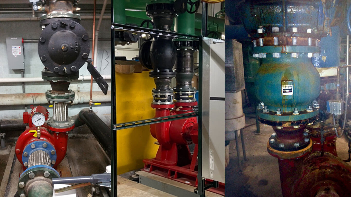
Depending on the application, check valves can get a bad rap. They are blamed for problems such as water hammer, vibration, reverse flow, leakage, or component wear and damage—all of which are harmful to downstream systems. However, the real cause of these problems usually stems from poor sizing and inadequate selection of the check valve for the application.
Most check valves are selected on line size and the desire for the largest valve flow coefficient available. Swing checks require a minimum rate of flow for the valve to function. If the flow is not sufficient to hold the disc in a fully open and stable position, the disc and associated internal parts will be in a constant state of motion (wobble). Insufficient flow results in premature wear, noisy operation, and vibration.
The solution to this problem is selecting a line size that produces sufficient flow. A general rule of thumb for water systems is to maintain a minimum of 7.5 feet per second (ft/sec) flow rate. If the system struggles to maintain that flow rate, it is sometimes recommended that the line size be reduced.
In piping systems containing other types of fluids, the flow requirements vary with the specific gravity of the media. The following formula can be used to approximate the minimum flow rates.
Flowmin (ft/sec) = 60 √V
V = specific volume of fluid (ft3/lb)
Silent check valves such as the Milwaukee Valve 1400 (Wafer) and 1800 (Globe) have slightly different flow requirements. Spring-loaded silent check valves are designed to provide a cracking pressure of 0.5 psi and to fully open at a flow velocity of 4 ft/sec.
All check valves should be installed in a location that has smooth and laminar flow conditions. The following general rules exist for check valve installations:
Downstream of a reciprocating pump or other turbulence-inducing device (elbow, tee, etc.):
- Swing type: Locate the valve a minimum of 10–12 diameters downstream of the device.
- Silent type: Locate the valve a minimum of 4–5 diameters downstream of the device.
Pipe fittings, elbows, reductions, etc., downstream of the valve:
- Swing type: Locate the elbow a minimum of 5–7 diameters downstream of the valve.
- Silent type: Locate the elbow a minimum of 2–3 diameters downstream of the valve.
For more information, visit www.MilwaukeeValve.com.


