
In recent years, the power needed to heat or cool buildings has fallen dramatically with the focus on reducing energy consumption and minimizing the environmental impact of HVAC installations. The flow rates in our installations are much lower now than in the past, especially if we use modulating controls on the terminal units.
Installations must be designed to guarantee a minimum flow rate for boilers and chillers so that their power output can be controlled and they keep running reliably. The same applies to variable-speed pumps requiring a minimum flow rate. Here, IMI Hydronic Engineering explains the issues around low flow rates in boilers, cooling units, and pumps; solutions to guarantee the minimum flow rate; and effective ways to control low flow rates.
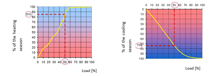
Alongside control precision and stability, the system designer should consider the overall output of the installation depending on the control type recommended for the terminal units. The flow rates in an installation are directly linked to the necessary power and the temperature difference. In general for 85 percent of the heating period and 73 percent of the cooling period, the installation operates below 50-percent load. For 50 percent of power, a flow rate on the order of 20 percent is sufficient.
Issues With Low Flow Rates
Care must be taken to guarantee the minimum flow rate required for boilers, chillers, and heat pumps. Variable speed pumps also require a minimum flow rate.
In terms of distribution, low flow rates will affect circulation speeds, which can result in problems with sediment and air pockets. Low flow rates result in a greater temperature drop from the source unit (boiler, chiller, or heat pump) to the terminal unit. Finally, control valve characteristics must be considered for controlling lower flow rates.
How to Guarantee the Minimum Flow Rate
One simple and popular way of ensuring a minimum flow rate is to use a “static” bypass for a constant flow rate through boilers or chillers. This bypass is sized to create a slight pressure drop that will create hydraulic decoupling between the source unit and the terminal units. Variable flow on the distribution units will not affect the flow rate in the chillers.
Operating chillers and boilers with variable flow improves production efficiency. To achieve this, a “dynamic” bypass is used that stays closed until the primary flow rate approaches the minimum flow rate required by the production equipment.
The table summarizes ways to guarantee the minimum flow rate. Each approach has benefits (plus signs) and drawbacks (minus signs).
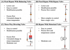
The minimum flow bypass with a balancing valve (A) should be adjusted below two thirds of the minimum flow rate to account for overflow when other control valves close.
As seen in (B), a bypass can be designed with a bypass valve that opens when the differential pressure passes the setpoint. These are diaphragm-spring technologies that are most effective with a proportional range on the order of 20 percent. This approach limits pumping costs and unwanted changes in the return temperature.
Three-way diverting valves (C) on the last terminal units are also used for maintaining minimum flow. This solution is easy to install but creates unwanted changes in the return temperature.
The best bypass design is with a motorized valve (D). The valve is opened according to the primary flow rate measured by a flow meter. As the flow rate approaches the acceptable limit, the valve gradually opens. The valve should not open or close too suddenly, causing surges.
Effective Control of Low Flow Rates
We need to accurately control the power output at low flow rates. For this, system designers must pay attention to the characteristics of two-way control valves. The two main criteria are the valve characteristic and the turndown.
The equal percentage (EQ%) flow characteristic is a way of compensating for the non-linearity of the exchangers. To control a flow rate between zero and 20 percent, an EQ% valve would operate between zero and 50-percent opening, which is 2.5 times more than a linear valve that is suitable for on-off application.
The other important criterion is the turndown. A turndown of 25 means that the minimum controllable flow rate is 4 percent of the nominal flow rate.
Controllable power is a function of the authority and the turndown of the control valve. The authority depends on the valve size and the available differential pressure. Authorities between 0.5 and 0.8 offer excellent control and can be achieved with differential pressure controllers or pressure-independent control valves.
For example, with an authority of 0.6 and a turndown of 25, the minimum controllable power is 20 percent, which corresponds to about 30 percent of the operating time. In other words, if no solutions are used to stabilize the available differential pressure in a circuit, the authority of a standard modulating control valve can go below 0.25, which could cause the control valves to operate in on-off mode with very low controllability for 30 percent of the operating time.
Compare Costs and Benefits
Our installations require us to manage lower and lower flow rates correctly or risk decreasing the life cycle of the equipment (pumps, boilers, and chillers). Compared with the cost of energy or premature wear, the investment needed to correctly control minimum flow rates is relatively modest.
To maintain a minimum flow rate and controllability in a hydronic system, IMI Hydronic Engineering recommends that system designers take into account minimum flow bypass using solutions like fixed bypass with bypass valves or bypass with motorized valves to get more precise flow and temperature control throughout the system. Particular attention should be paid to the characteristics of the control valves. High turndown, the EQ% flow characteristic, and high control valve authority are the criteria that will ensure effective control of exchanger power for most of the operating time of HVAC installations.
For more information, visit www.imi-hydronic.com.