
The ultimate goal of every heating and cooling installation is to provide the desired indoor climate at the lowest possible energy cost. Today’s advanced control technology means that, in theory, achieving this goal is possible. In practice, however, even the most sophisticated controllers do not always perform as promised. The result is lower-than-desired comfort level and high energy expenditure. The controllers can only perform their functions as specified if the three key conditions for hydronic control are fulfilled:
- The design flow must be available at all terminals.
- The differential pressure across control valves must not vary too much.
- Flows must be compatible at system interfaces.
The best way to attain these three conditions is to perform a balancing procedure to ensure that the plant performs and operates as specified by the designer. Balancing can help find and remove issues ranging from incorrectly implemented balancing calculations to assembly errors, such as incorrectly installed check valves, and blocked filters. The balancing procedure allows you to immediately reveal the effects of any disturbances, identify the cause, and take corrective measures. This article summarizes IMI TA’s expertise in the three key hydronic conditions, describes how to identify when the conditions are not being met, what caused the problem, and how to solve it.
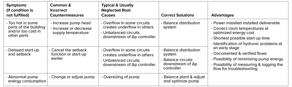
Condition 1
To ensure that the design flow is available at all terminals, hydronic balancing is necessary. Hydronic balancing prevents overflows in certain circuits from causing underflows in others. Balancing helps to detect possible oversizing of pumps and verifies that the plant provides the functions and performance as intended. See Table 1 for symptoms and solutions.
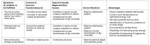
Condition 2
For stable and accurate control, the differential pressure across the control valves must not vary too much. Again, hydronic balancing is required to meet this condition. In fact, hydronic balancing is the only way to identify and resolve the real causes of operational problems in the plant. See Table 2 for symptoms and solutions.
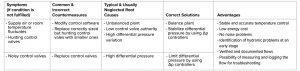
Condition 3
For perfect hydronic control, flows must be compatible at system interfaces. To fulfil this condition, hydronic balancing is necessary so that the installed power in the plant can be delivered. The balancing procedure allows you to localize and resolve any hydronic problems. It also reveals possible oversizing of pumps and helps reduce pumping costs. See Table 3 for symptoms and solutions.

Other Benefits
Achieving the three key hydronic conditions can also bring the following benefits:
- Faster system balancing and commissioning using the right balancing products and following proper engineering methods
- Quicker return on investment and lower risk for owners with a well-optimized system, detailed commissioning reports, and happy tenants
- Added flexibility for any system changes and future expansion (with no rebalance needed) for the designers and contractors
IMI TA’s Engineering Support Centers provide free help with project review for functional checks, possible problems, solutions, takeoff, selections, preset, and energy calculations to simplify the overall installation and balancing/commissioning process: https://www.imi-hydronic.com/sites/EN/international/Pages/Engineering-Support-Center.aspx
IMI Hydronic Engineering invites you to attend Hydronic College to get in-depth product training: https://www.imi-hydronic.com/sites/EN/en-us/knowledge-centre/Pages/Hydronic-College.aspx
For more information, visit www.imi-hydronic.com, call 855-55-ASK TA (855-552-7582), or email trainings.na@imi-hydronic.com.